Ethernet, defined by IEEE 802.3, is the foundation of IP-based media networks. In the broadcast world, the shift from coaxial SDI cabling to Ethernet over copper and fiber has enabled scalable, high-bandwidth connectivity for uncompressed video, audio, and data. Fiber optics support longer runs and higher bandwidth, while copper can be used for shorter connections. NICs (network interface cards) in servers, switches, and media devices determine throughput, buffering, and PTP awareness—critical for SMPTE 2110 systems.
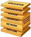
Now that we have our network highway in place, we need to be able to use it. That is accomplished by channel coding: a stream of highs and lows are created by the NIC and convey data that one node wants to send to another. This usually includes extra information that tells the receiving node how to recover bits that have been lost, and how to synchronize with the sender. At this level, the channel code can be thought of as a conveyer belt from one node to the next. The ends of the conveyor belt can be thought of as the device’s NIC. We will conceptualize that data packets are a series of boxes, each packed within another.
The Internet Protocol (IPv4, RFC 791) organizes packets into a format that routers and switches can understand. IP addresses, subnet masks, and routing tables determine how data flows through a facility. In a broadcast plant, IP networks are usually private and highly controlled, ensuring low latency and predictable performance. Understanding IP addressing and routing helps engineers design fault-tolerant systems that avoid bottlenecks and allow seamless device-to-device communication.
The User Datagram Protocol (UDP, RFC 768) is a lightweight, connectionless protocol ideally suited for real-time applications like video and audio. Unlike TCP, UDP does not require acknowledgments or retransmissions, which would add latency and jitter. Instead, media systems rely on redundancy, buffering, and error correction at higher layers to handle packet loss. This tradeoff makes UDP the backbone of SMPTE 2110 transport, allowing video and audio to move in real time without delay.
Multicast networking allows a single data stream to be delivered to multiple receivers without duplicating packets for each destination. In broadcast IP systems, this is essential for efficiency—dozens of devices can subscribe to the same live video feed without overloading the switch. IGMP (Internet Group Management Protocol) manages multicast group membership, letting devices "join" and "leave" streams dynamically. Proper multicast configuration is one of the most important skills in 2110 deployments.
RTP (RFC 3550) provides the timing and sequencing needed to carry video and audio payloads over UDP. Each RTP packet includes sequence numbers to detect packet loss and timestamps for synchronization. For media engineers, understanding RTP headers is key to troubleshooting stream integrity. In practice, RTP forms the “wrapper” around 2110 essence flows—video, audio, or data—making sure receivers can reassemble them in real time.
IEEE 1588, or PTP, is the heartbeat of SMPTE 2110 systems. It allows all devices in a network to synchronize to sub-microsecond accuracy, replacing the black burst and word clock of SDI systems. A PTP grandmaster clock distributes timing signals, while boundary and transparent clocks within switches ensure accuracy across the network. Without PTP, it would be impossible to keep uncompressed audio and video streams aligned in real time.
2110 software package isn’t a single installer but a layered stack that turns standard IT hardware into a broadcast-grade IP plant: at the base are OS and NIC drivers with hardware timestamping (often plus Rivermax/DPDK for high-rate I/O); timing is provided by IEEE-1588 PTP using the SMPTE ST 2059 profile (PTP client/daemon and GM management); the fabric is configured for multicast with IGMP/PIM, QoS/DSCP, and optional ST 2022-7 hitless redundancy; media endpoints run 2110-20/30/40 RTP stacks with SDP and pacing; discovery and routing come from NMOS services (IS-04/05, plus IS-07/08/09/10 for events, audio mapping, system params, and auth); security layers in mTLS/OAuth/PKI; and observability adds PTP/flow telemetry, packet analysis, and alarms—delivered either as a vendor ecosystem (e.g., Magnum/VSM/HOME/Convergent) or a DIY mix of open services and commercial I/O SDKs.
SMPTE ST 2059 adapts PTP specifically for the broadcast industry. Part 2059-1 defines how wall-clock time (UTC) is distributed, while 2059-2 specifies how PTP supports video and audio synchronization. Together, these standards replace traditional sync pulses like tri-level sync. They are the direct bridge between legacy SDI timing and IP-based workflows, ensuring frame accuracy across all flows.
ST 2110-10 establishes how PTP and 2059 timing integrate with media flows. It defines synchronization requirements across video, audio, and data, ensuring all elements of a program line up precisely at the point of playout. This standard ties together the concepts of PTP and essence flows, creating the foundation for a deterministic broadcast IP system.
ST 2110-20 describes how uncompressed video is packetized and transported over RTP/UDP/IP. Unlike SDI, which multiplexed video, audio, and data in one cable, 2110 separates them into distinct streams. This makes video flows independent and flexible for routing, switching, and monitoring. Engineers must understand pixel groupings, packetization, and network bandwidth requirements, since a single 4K video stream can demand over 10 Gb/s.
ST 2110-30 standardizes uncompressed PCM audio over IP, built on AES67. It allows multichannel audio streams to move independently from video, providing enormous flexibility for mixing and routing. Broadcasters can route audio and video separately or even remap channels in real time. Compatibility with AES67 also ensures interoperability with audio-over-IP systems already in use.
Ancillary data, once carried in the blanking intervals of SDI, is separated into its own flow under ST 2110-40. This includes closed captions, timecode, and SCTE ad-insertion triggers. Keeping ancillary data independent allows it to be processed, filtered, or substituted without affecting the video essence. For broadcasters, this separation enhances flexibility and makes regulatory compliance easier.
ST 2110-21 defines how video packets should be shaped to avoid jitter and buffer overflows in network equipment. It ensures that even uncompressed UHD flows can be carried predictably across shared infrastructure. ST 2110-22, on the other hand, allows for compressed video (using JPEG XS), reducing bandwidth requirements while maintaining visually lossless quality. This is critical for remote production and wide-area transport where bandwidth is limited.
SDP (Session Description Protocol) defines the parameters of each media flow—IP addresses, ports, codecs—so devices can join streams correctly. AMWA’s NMOS standards add automation and intelligence: IS-04 handles discovery and registration (like DNS for broadcast devices), while IS-06 manages connection and flow control. Together, these standards make large-scale 2110 systems manageable, allowing operators to find, connect, and reroute hundreds of devices dynamically.
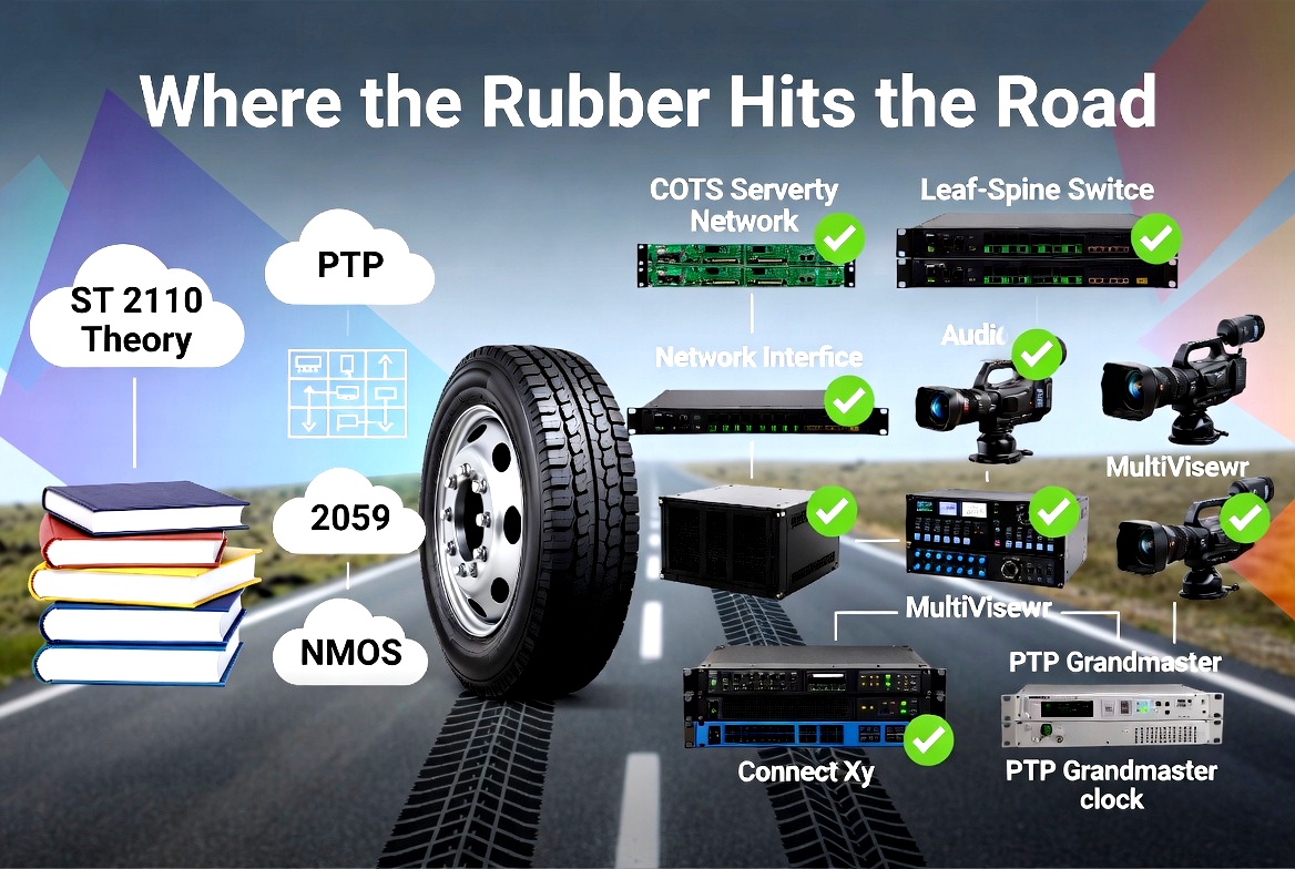
Finally all the pieces come together. Video switchers, audio mixers, recorders, and wrappers interface with SMPTE 2110 flows to form a complete broadcast chain. Remote I/O extends the system across facilities or continents, enabling distributed production. By this point, the engineer should understand how each protocol and standard contributes to a flexible, IP-based media plant. Case studies from broadcasters provide real-world context on how 2110 is deployed at scale.